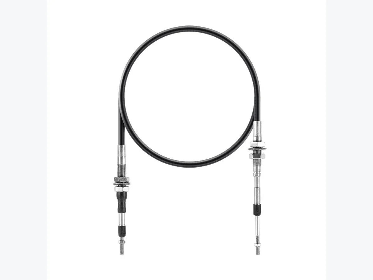
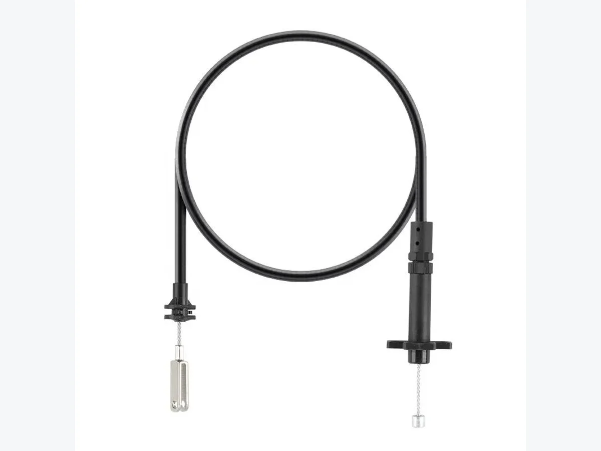
Product Overview
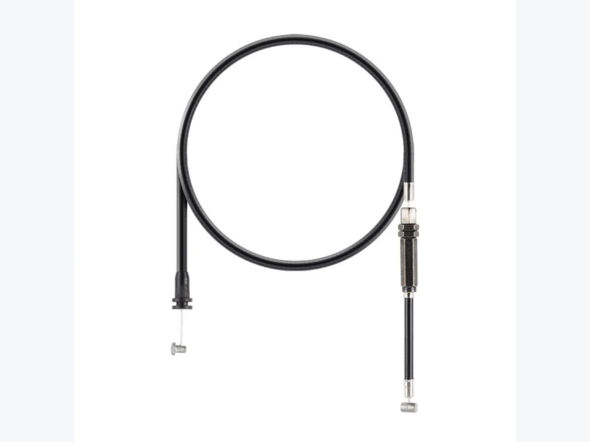
Push Pull Control Cable is used when a mechanical control must transmit movement in two directions through a protected cable route. Compared with a basic pull cable, the procurement focus is stroke, neutral position, mounting interface and terminal alignment. Buyers should treat the cable, housing and mounting hardware as one assembly.
Procurement Notes
- Useful for equipment controls where both push and pull movement are needed.
- Terminal alignment and thread details should be confirmed before quotation.
- A sample can reduce risk when the original cable has special mounting hardware.
Buyer Confirmation Points
- Stroke and neutral position
- Housing length and mounting distance
- Thread or terminal dimensions
- Control function and route
Commercial Sourcing Handoff
Once the bidirectional function and stroke are confirmed, use Custom Mechanical Control Cables for the OEM sourcing route. That page collects drawing or sample evidence, route constraints, terminal geometry, quantity and packaging without changing this product page’s role as the configuration reference.
Push Pull Control Cable RFQ Checklist
For push pull control cable specifications, separate the moving inner cable from the fixed outer casing. The RFQ should show overall length, housing length, working stroke, neutral position, routing path and the terminal geometry at both ends. If the request is for a replacement cable, include photos of the removed sample, the lever or actuator connection, the mounting bracket and any adjuster or bulkhead fitting.
Useful comparison pages include Control & Brake Cables, Sample-Based Cable Matching and the Control Cable RFQ Checklist. These links help buyers prepare drawings, route photos and sample notes before sending a Request a Quote.
Buyer Search Notes
Buyers searching for push pull control cable specifications should separate overall length, housing length and stroke, then provide inner cable diameter, outer casing style, terminal photos, route notes and sample photos when available. Compare the Control & Brake Cables category and the Push Pull Control Cable Specifications for RFQ guide before submitting a Request a Quote.
Control Cable Design Summary
Custom control steel cable design should begin with the movement function and installation route. Separate housing length, exposed inner cable, working stroke and mounting positions. Then show the terminal type, adjuster, bulkhead fitting, casing end and actuator connection. A drawing, measured sketch or sample helps confirm the arrangement when the equipment interface is difficult to describe in words.
For a sample-based replacement, compare Bowden Cable Assembly, Mechanical Control Cable Applications and the Control Cable RFQ Checklist for OEM Buyers before using the Request a Quote page.
Push Pull Control Cable vs Bowden Cable
Push-pull control cable requests should identify bidirectional movement, neutral position and stroke. A Bowden cable request may focus more on the flexible housing route and inner cable movement. The two product families can look similar in a catalogue, but the mechanism, casing support and terminal interfaces determine which configuration should be reviewed. Use the Mechanical Control Cable Applications page when the function is still being selected.
Housing Length, Inner Cable and Stroke
Measure overall length from clearly labeled reference points, then record housing length, exposed inner cable and working stroke separately. If the cable is removed from equipment, note whether it is worn, stretched or bent. A route photo with the neutral and working positions marked is often more useful than a single length value.
Terminal Type and Routing
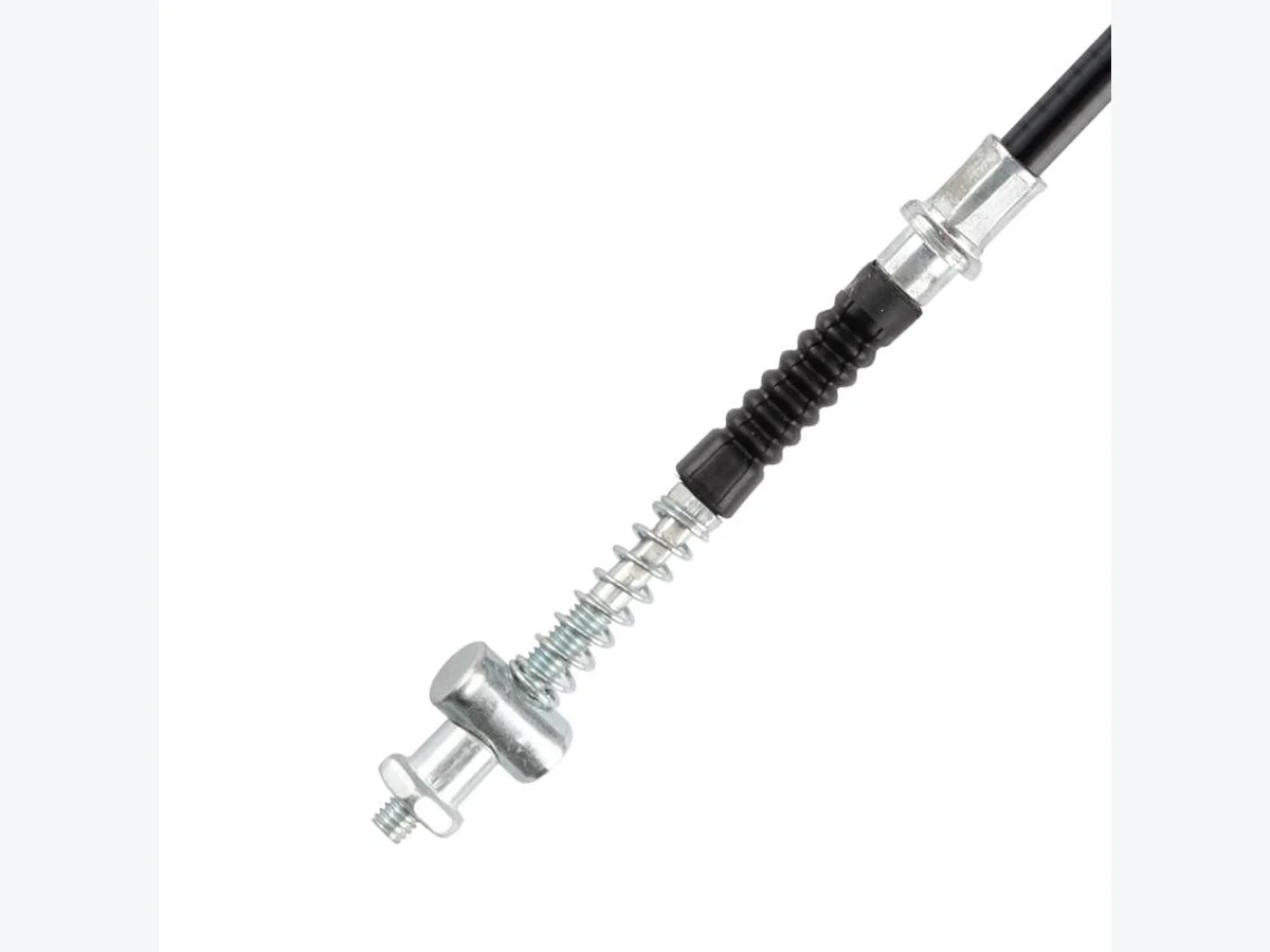
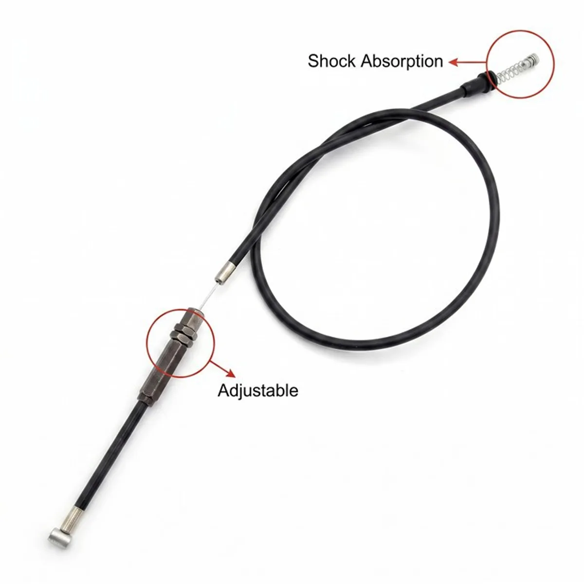
Show both inner cable terminals and casing-end fittings. Threaded rod ends, eye or clevis-style connections, adjusters, bulkhead fittings, springs, boots and end caps should be identified by side and orientation. Include the mounting bracket, actuator connection and tightest bend in the route so the terminal geometry is reviewed with the cable path.
Drawing or Sample Requirements
For an OEM request, include the current drawing revision, mounting dimensions and terminal orientation. For a replacement request, include a full sample photo, close-ups of both ends, a measured sketch and the equipment interface. Sample-Based Cable Matching can help organize a request when the original drawing is not available.
OEM Control Cable RFQ Checklist
- Push and pull function, neutral position and stroke
- Overall length, housing length and mounting-point distance
- Inner cable, outer casing and terminal details
- Route, actuator connection and application environment
- Drawing or sample photos, quantity and packaging notes
Common Mistakes
Do not quote from a generic cable diameter while omitting stroke or housing length. Do not assume both ends use the same terminal, and do not hide a damaged sample condition. Mark approximate measurements and identify any open fitting question before sending the RFQ.
Related Products and RFQ
Compare Bowden Cable Assembly, Brake Cable Assembly, Control & Brake Cables, End Fitting Installation and Custom Mechanical Control Cables. When the movement and dimensions are ready, use Request a Quote.